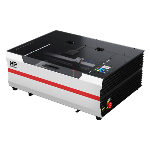
A fiber laser uses pump light to energize an optical fiber that contains a gain material. Stimulated emission amplifies laser light inside that fiber. The machine then directs and focuses the output onto a workpiece, where absorbed energy changes the surface or removes material.
This guide focuses on the pulsed, ytterbium-based galvo systems commonly used for metal marking and engraving. Many operate near 1064 nanometers (nm). Industrial fiber cutting and welding systems share the principle of optical amplification, but use different power levels, processing heads and supporting equipment.
Understanding that distinction matters: a machine that marks a stainless-steel tag is not automatically equipped to cut a sheet of stainless steel.
How Does a Fiber Laser Work?
The word fiber refers to the light-guiding gain medium, not merely a cable carrying light from another kind of laser. In common industrial sources, rare-earth ions are incorporated into the glass core. They are not a coating painted onto its outside.

1. Pump diodes supply energy
Semiconductor diodes turn electricity into pump light. This light supplies energy to the active fiber; it is distinct from the processing laser output. Optical couplers or combiners guide it into the appropriate region of the fiber.
2. The fiber guides the light
The fiber's refractive-index structure confines and guides light. In common double-clad designs, pump light travels through an inner cladding surrounding the smaller active core. As it crosses the core, some of its energy is absorbed. The signal light is guided principally in the core; the pump and signal do not simply follow one identical path.
3. The gain material absorbs pump energy
Ytterbium ions absorb pump photons and reach excited states. Pumping maintains an excited population from which optical gain can be obtained. Some stored energy is lost through other processes, so electrical input power is not equal to usable laser output.
4. Stimulated emission amplifies a signal
An appropriate optical signal stimulates excited ions to emit into the signal's optical mode, increasing its power. An oscillator provides optical feedback; an amplifier boosts a signal supplied to it. These are related functions, not interchangeable descriptions of every component.
5. The source establishes the output
Some fiber oscillators use fiber Bragg gratings as wavelength-selective reflectors. Other systems amplify a seed signal through additional stages. The source design determines the available wavelength, pulse behavior and operating range. It is misleading to describe every fiber laser as one identical cavity with two mirrors.
6. Delivery optics concentrate the output on the workpiece
In a typical galvo marker, collimating optics prepare the beam and two scanning mirrors steer it across the marking field. An F-theta scan lens focuses it onto the working plane. Software coordinates the beam position and emission to create the design. The energized fiber generates or amplifies light; the scanning head positions that light.
The Laser Source, Scanning Head and Lens Do Different Jobs
| Subsystem | What it does | Why it matters |
|---|---|---|
| Laser source | Contains the pumping and gain stages and associated controls | Defines the usable power, pulse and frequency envelope |
| Beam preparation optics | Collimate the output and, where fitted, adjust its diameter | Affect how the downstream optics are illuminated |
| Galvo scanning head | Steers the beam with moving mirrors | Positions patterns without moving a heavy gantry over each line |
| F-theta lens | Focuses the scanned beam over a specified field | Affects field size, working distance and achievable spot size |
| Focus and fixtures | Locate the part relative to the working plane | Make placement and processing more repeatable |
| Safeguarding and extraction | Control access to radiation and capture processing emissions | Must suit the complete installation and material |
Pump diodes and active fiber are internal parts of the source, not separate user-serviceable accessories. Likewise, a visible enclosure does not by itself establish a machine's safety classification.
Why a larger marking area can change the result
With comparable beam diameter and beam quality, a longer-focal-length lens typically produces a larger spot. Spreading pulse energy over a larger area reduces fluence, which means energy per unit area. A larger marking field can therefore trade some fine-detail or removal capability for coverage.
Do not select a lens by field dimensions alone. Check source wavelength, mounting compatibility, required beam diameter, working distance and calibration. Comparing a 110 × 110 mm scanning lens with a 200 × 200 mm field lens should start with the size of the artwork and the smallest feature that must remain legible.
Set focus using the machine's specified procedure. A red framing light helps position artwork; it does not necessarily verify the infrared beam's focal plane. Curved parts may require a compatible fiber-laser rotary attachment, appropriate fixtures or dynamic focusing.
CW, Q-Switched and MOPA: Understand the Labels
These terms describe different aspects of a laser. CW means continuous-wave output. Q-switching is a method of producing pulses by changing cavity losses. MOPA means master oscillator power amplifier: a seed source followed by amplification.
A MOPA can use different kinds of seed sources, including a Q-switched oscillator. Consequently, “Q-switched versus MOPA” is useful retail shorthand but not a strictly exclusive scientific classification. In the marking-machine market, the comparison usually means a conventional Q-switched source versus a source sold with selectable pulse widths. Check the actual source specification, not just its label.
The RP Photonics explanation of MOPA architecture, by Dr. Rüdiger Paschotta, describes this oscillator-and-amplifier relationship. For the purchasing context, see Monport's MOPA and conventional fiber-source comparison.
| System | Typical role | Important distinction |
|---|---|---|
| Pulsed galvo marker | Logos, serial numbers, codes and surface engraving | Part geometry, contrast and cycle time drive selection |
| Adjustable-pulse-width fiber system | Process development requiring additional pulse control | Not every pulse width is available at every power and frequency |
| Deep-engraving setup | Repeated material removal to create a recess or relief | This is an application configuration, not a separate gain-medium category |
| Industrial fiber cutter | Separating metal sheet or tube | Often uses high-power CW output, a cutting head, assist gas and dedicated motion control |
Manufacturers offer distinct infrared nanosecond source families with different pulse and power capabilities. A generic wattage label is not a complete source specification.
How the Beam Makes a Mark on Metal
The workpiece absorbs part of the incident energy and reflects part of it. Wavelength, surface finish, temperature and material composition affect that balance. Concentrating the absorbed energy can alter an oxide layer, remove a coating or remove the underlying metal.
| Process | Main effect | What to check |
|---|---|---|
| Annealing marking | Controlled heating produces an oxide-related mark on suitable metals, generally without substantial removal | Contrast, surface condition and corrosion requirements |
| Coating removal | Removes a surface layer to expose a contrasting substrate | Whether the exposed substrate is damaged or needs protection |
| Engraving | Removes substrate material to form a recess | Measured depth, roughness, edge quality and processing time |
| Oxide color marking | Creates surface films that produce color on suitable metals | Alloy, repeatability, viewing conditions and durability |
“Marking” is an umbrella term. “Etching” is used inconsistently by suppliers, so ask whether the proposed process removes material, changes the surface or removes a coating. A dark mark is not proof of engraving depth.
Color marking on stainless steel is not full-color printing. Adjustable pulse control can help develop a process, but it does not guarantee a particular palette on every finish. Approve samples under the lighting and cleaning conditions the finished product will encounter. Monport's metal marking and engraving guide provides related application context.
How Power, Frequency and Pulse Width Work Together
The key distinction is between energy delivered over time, energy in one pulse and the area receiving it. A percentage in software is a command to the source, not a universal measurement of watts at the workpiece.

Average power and pulse energy
For a steady train of equivalent pulses, pulse energy equals average optical power divided by repetition rate:
Pulse energy (J) = average optical power (W) / repetition rate (Hz)
Illustrative calculation, not a machine setting: if a source actually delivers 20 W at 20,000 pulses per second, each pulse carries 0.001 J, or 1 mJ. If it maintains 20 W at 40,000 pulses per second, each pulse carries 0.5 mJ. The calculation assumes steady output and does not override the source's pulse-energy limits. See RP Photonics on pulse energy, by Dr. Rüdiger Paschotta.
Pulse duration and peak power
Delivering the same energy in less time raises power during the pulse. For a simplified rectangular pulse:
Peak power (W) ≈ pulse energy (J) / pulse duration (s)
A hypothetical 1 mJ pulse lasting 100 ns corresponds to 10 kW during that idealized pulse—not 10 kW of continuous output. Real pulses have shapes, so calculating true peak power requires the waveform and the duration definition.
Shorter pulses can limit heat spreading during a pulse, but repeated pulses can still accumulate heat. Reducing pulse width does not automatically produce a cooler or better mark if energy, overlap or pass count also changes.
Scanning speed and hatch spacing determine overlap
At constant speed, the approximate distance between pulse centers along a scan is:
Pulse spacing (mm) = scan speed (mm/s) / repetition rate (Hz)
For example, 1,000 mm/s at 50,000 Hz gives 0.02 mm between pulse centers. Whether the pulses overlap depends on spot size. Hatch spacing is different: it separates adjacent fill lines. Both affect coverage and heat buildup.
| Change | Likely relationship | Caution |
|---|---|---|
| Raise frequency at fixed average power | Less energy per pulse; closer pulses at fixed speed | Actual power may vary with the selected operating point |
| Lower speed | More exposure and overlap along the scan | May increase melting, heat tint or cycle time |
| Reduce hatch spacing | More scan lines cover the same filled area | More heat and time do not necessarily improve contrast |
| Add passes | Can increase removal | Heat, debris and changing surface depth can alter later passes |
| Change lens or focus | Changes energy concentration at the surface | Previously approved settings require revalidation |
Use the laser-source manual to establish valid combinations before running a parameter grid. The broader MOPA parameter-setting guide is a starting point for learning the controls, not permission to copy a recipe between unlike sources.
Which Materials Suit a Fiber Laser?
For a conventional near-infrared pulsed marker, metal is the main starting point. Compatibility still means a specific material-process combination, not a blanket promise for every grade.
- Stainless steel: suitable for several marking and removal processes. Verify contrast and any corrosion or cleaning requirements.
- Aluminum: bare and anodized surfaces behave differently. A successful anodized mark does not establish performance on bare aluminum.
- Copper, brass and precious metals: confirm source suitability, reflection management and achievable results on the actual alloy.
- Coated or plated metal: identify the coating and assess processing emissions as well as the exposed surface.
- Plastics: resin, pigments and additives determine response. Obtain supplier confirmation and safety information for the exact grade.
Clear acrylic and many glasses transmit much of the near-infrared light rather than absorbing it effectively. Standard 1064 nm markers are generally not the starting choice for these materials. A CO₂ system is often appropriate for clear-acrylic processing and glass surface engraving; a common blue-diode laser is not a direct replacement for those tasks.
Fiber versus CO₂: compare the intended application
| Question | Pulsed fiber galvo marker | CO₂ gantry engraver/cutter |
|---|---|---|
| Common starting material | Bare and coated metals; selected plastics | Wood, acrylic and other verified compatible nonmetals |
| Typical wavelength | Near 1064 nm for many marking sources | Often 10.6 µm |
| Common task | Codes, personalization, surface marking and engraving | Sheet cutting and larger-area engraving |
| Important limitation | Not a general wood or clear-acrylic cutter | Typical desktop systems are not bare-metal deep engravers |
Galvo and gantry describe beam positioning, not the gain medium: CO₂ galvo systems and other combinations also exist. See the CO₂, fiber and diode comparison when choosing between product categories.
Example: Planning a Stainless-Steel Tag Test
This is an illustrative validation workflow, not a reported Monport experiment or a universal settings recipe. Its purpose is to turn the physics into a repeatable decision.
- Define success. Decide whether the tag needs a readable surface mark or a measurable recess. Set the required contrast, depth if applicable, and acceptable cycle time.
- Identify the sample. Record alloy grade, thickness, finish, coating status and supplier batch. Use representative scrap, not a customer's finished item.
- Confirm the safe setup. Use approved guarding and extraction. Fix the sample securely, select the correct lens configuration and establish focus by the manufacturer's procedure.
- Start within documented limits. Use a manufacturer-supported starting point for that source and material. Hold lens, focus, artwork, hatch and pulse width constant while evaluating a small power-speed matrix.
- Refine the promising region. Investigate frequency or pulse width in a separate controlled comparison. Record all settings because a changed frequency may also change available power or pulse energy.
- Evaluate after cleaning. Follow a material-appropriate cleaning procedure; inspect readability, roughness, distortion and unwanted discoloration. Measure depth if it matters. Validate machine-readable codes with the required verification method.
- Repeat before approving production. Test multiple samples and actual placement positions. Save the approved artwork, source model, lens, fixture, settings, photographs and cycle time.
If a mark is shallow or inconsistent, verify focus, fixture stability and optics condition before assuming the source lacks power. If edges melt, consider accumulated exposure and overlap rather than changing several controls simultaneously. These are diagnostic possibilities, not a diagnosis of every defective mark.
Choose the System Around the Result You Need
For more application examples, start with common uses for fiber lasers. Then compare candidates using a sample specification instead of an isolated wattage number.
- Serial numbers and logos: prioritize readable detail, positioning, repeatability and total handling time.
- Deep engraving: request measured depth and cycle time on the exact material. Evaluate removal efficiency and finish, not only maximum output.
- Color or delicate surface effects: investigate adjustable pulse control and ask for repeatable samples on the same grade and finish.
- Cylindrical parts: check rotary compatibility, diameter range, clearance and software support.
- Metal sheet cutting: evaluate a purpose-built cutting platform, including gas, bed, head and motion requirements.
Once those requirements are defined, compare Monport fiber laser engravers. Ask for the source's usable pulse-energy and frequency ranges, supported lenses and complete-system safety documentation along with power specifications.
Invisible Light Still Requires Engineered Protection
A 1064 nm processing beam cannot be judged by sight. Direct exposure and reflections can injure eyes or skin; processing can also create fumes, particles and ignition hazards. A red preview light and ordinary tinted glasses do not control these risks.
- Use a properly designed, wavelength-appropriate protective enclosure and functioning interlocks. Do not bypass safety features.
- Have a qualified person assess any installation with accessible hazardous radiation, including beam paths, reflections and access control.
- Select protective eyewear for wavelength, required optical density and operating conditions under the safety assessment. Eyewear is not a substitute for engineered controls.
- Capture emissions at the source using extraction appropriate to the material and contaminants. An SDS is useful input but does not automatically establish safe laser-processing conditions.
- Do not process unidentified materials or unapproved coatings. Keep combustible items away and follow fire-prevention and supervision requirements.
- Follow the complete machine's classification label and manual. A Class 4 source inside a suitably designed system does not make an arbitrary added cover a Class 1 enclosure.
When reviewing a fiber-laser enclosure with door-opening protection, confirm compatibility and the safety performance of the assembled installation. For U.S. workplace guidance, consult OSHA's laser-hazard standards resources and the applicable machine documentation.

Frequently Asked Questions
Why is the processing beam invisible when the preview is red?
Many metal-marking fiber lasers operate near 1064 nm, outside the visible spectrum. The red framing light is usually a separate alignment source. Its visibility does not indicate whether the infrared processing beam is safe or inactive.
Can a fiber laser cut metal as well as engrave it?
Industrial fiber cutting systems can cut metal, but a compact pulsed marker is not an interchangeable substitute. Some marking systems can cut thin stock under approved conditions. Confirm the exact alloy, thickness, edge quality and cycle time with the manufacturer.
Does a fiber laser need gas or water cooling?
Many compact pulsed marking machines are air-cooled and do not require assist gas for routine marking. Industrial cutting and welding systems have different cooling and gas requirements. Follow the specifications for the complete machine, not assumptions based on the fiber laser label.
How deep can a fiber laser engrave?
There is no universal depth rating for all materials and machines. Depth depends on the alloy, delivered pulse energy, spot size, passes, focus management and acceptable processing time. Request a measured sample made on the proposed system.
Is a 100W fiber laser more precise than a 30W model?
Not necessarily. Higher average power may improve removal rate or production speed, but detail also depends on beam quality, lens, focus, pulse characteristics and calibration. Compare the same artwork on the same material rather than using wattage as a precision rating.
The Practical Takeaway
A fiber laser's gain medium supplies amplified light; its source controls the output; its optics position and concentrate it; the material determines how absorbed energy changes the surface. Those stages explain why changing a lens, frequency or finish can alter a result even when the wattage stays the same.
Before purchasing or approving a production recipe, define the material and required finish, verify the complete safety setup, and evaluate repeatable samples. That gives you a useful specification—not just a larger number on a product page.