Laser engraving silicone is possible, but a clean mark is not produced by choosing the highest laser power. It is produced by creating enough controlled surface change for contrast while preserving the part's geometry, flexibility, feel, and intended function. For many silicone components, a 355 nm UV laser is the first technology worth testing because the material often absorbs the shorter wavelength more effectively than it absorbs a conventional near-infrared fiber laser. The process can therefore use less unwanted bulk heating.
That does not mean every silicone will accept a sharp, permanent UV mark. “Medical-grade silicone” describes a family of formulations, not one identical substrate. Base polymer, cure chemistry, fillers, colorants, laser-sensitive additives, surface texture, transparency, and post-cure conditions can all change the response. A process that produces dark contrast on one black earplug may create a pale mark on a translucent catheter component—or no useful contrast at all.
The practical conclusion is firm: for medical silicone laser marking, UV is usually the best starting point when heat damage is the main risk. A purchase decision should still be released only after testing production-representative samples against written acceptance criteria.

“Engraving” and “Marking” Do Not Always Mean Material Removal
People searching for laser engraving silicone often use “engraving” as a general term for creating any permanent laser-applied image. In production engineering, however, the word can imply measurable material removal. That distinction matters on seals, tubing, masks, valves, and other functional parts. A recessed mark may be acceptable on a thick non-contact area but inappropriate on a sealing surface or a thin wall.
The RFQ should therefore describe the required outcome rather than relying on the word engraving. State whether the process should create a color change, a shallow tactile feature, or a controlled recess. Add a maximum permitted depth or a “no detectable material removal” requirement when appropriate. Also define whether the mark is decorative, human-readable, machine-readable, or part of a regulated identification workflow. This language prevents a supplier from optimizing for visual depth when the actual requirement is low-impact contrast.
For medical parts, “marking” is often the safer default specification until testing proves that removal is both necessary and acceptable.
UV Laser Marking Silicone Is the Better Starting Point When Heat Damage Is the Main Risk
Silicone parts can fail cosmetically or functionally when a marking process deposits too much heat in the wrong place. Common symptoms include yellow or brown discoloration, glossy melted edges, a rough crater, soot, loss of transparency, and a surface that feels sticky after processing. Thin walls can distort, while raised seals or flexible lips may lose their intended shape.
A UV laser operates at a shorter wavelength than the 1064 nm output commonly used by fiber marking systems and the 10.6 µm output commonly used by CO2 systems. In suitable formulations, the shorter wavelength supports a more localized interaction and a smaller focused spot. This is why the process is often described as cold laser marking. The phrase is useful, but it should not be read literally: the process can still generate heat, and poor parameters can still damage a part.
For a buyer, the benefit is not the slogan. It is a wider chance of obtaining contrast with limited melting or carbonization. The specification should therefore request evidence of acceptable surface change, not merely a machine labeled “UV.”
Fiber, CO2, and UV Lasers Do Not Produce the Same Silicone Result
|
Laser route |
What it may do on silicone |
Main concern |
When to test it |
|
355 nm UV |
Localized color change or fine surface modification with relatively low heat input |
Contrast remains formulation-dependent; excessive passes can still roughen or discolor the surface |
First choice for small text, logos, graduations, and codes on heat-sensitive molded parts |
|
1064 nm fiber or MOPA fiber |
May mark specially formulated or pigmented silicone, but untreated silicone can absorb poorly |
Weak contrast, local overheating, or inconsistent response between material lots |
When the supplier confirms laser-responsive additives or sample tests show a stable window |
|
10.6 µm CO2 |
Strong surface heating, engraving, or ablation |
Melting, charring, wide heat-affected edges, debris, and tactile change |
Selected nonmedical decorative or cutting tasks; evaluate cautiously for functional medical parts |
|
Ink, pad print, or label |
Adds visible information without laser interaction |
Adhesion, abrasion, solvents, migration, consumables, and possible detachment |
When direct material contrast is impossible and the added material is acceptable |

This comparison is a screening tool. It is not permission to mark a released medical product. A laser can change surface chemistry and topography even when the mark looks smooth to the unaided eye. If the marked region contacts a patient, a drug path, breathing gas, or a cleaning fluid, the change must be assessed within the manufacturer's risk-management and biological-evaluation processes.
Silicone Formulation Matters More Than the Generic Material Name
Pigment and additives control whether useful contrast is possible
White, black, transparent, and colored silicones do not respond in the same way. Some formulations contain additives designed to produce a controlled color change under a particular wavelength. Others were never designed for direct marking. Even a change in pigment supplier or loading can shift the usable parameter window.
Ask the silicone supplier for the exact grade, color code, cure system, relevant processing history, and any available laser-marking guidance. When the formulation is confidential, establish a controlled material identifier and require change notification. “Same color” is not adequate incoming-material control.
Surface finish changes appearance and scan performance
A polished mold surface, matte texture, parting line, release-agent residue, or post-mold coating can change contrast and edge definition. A code that scans on a flat test plaque may fail on a curved tube because illumination and focus vary across the symbol. Production trials should therefore use final geometry rather than only flat coupons.
Thickness and function define the acceptable process window
A thick protective earplug body has more thermal and mechanical margin than a thin sealing membrane. A graduation mark on tubing has different acceptance criteria from a decorative logo on a reusable case. The process window must be linked to the function of the marked zone: sealing, flexing, optical inspection, skin contact, or fluid contact.
Laser Engraving Silicone Products Requires Application-Specific Decisions
Catheters and flexible tubing prioritize geometry and flex life
Depth marks, size indicators, lot information, and orientation marks can help clinicians and manufacturing teams, but a catheter or tube must continue to bend without initiating cracks at the mark. Testing should include repeated flexing, extension where relevant, cleaning or conditioning, and inspection under magnification. Mark location should avoid highly strained sections unless the design has been qualified for that use.
Respiratory masks and seals prioritize comfort and cleanability
Silicone mask cushions and sealing components touch skin and are cleaned repeatedly. A rough mark in the sealing zone can create an undesirable tactile change or become more difficult to clean. Place identification on a low-contact area where possible, and define maximum roughness or simply prohibit detectable surface relief if that is more practical.
Silicone logo marking on custom hearing protection must preserve the finish

Custom silicone earplugs and hearing-protection products often need a manufacturer logo, customer logo, left/right identifier, or serial reference. Here, the challenge is not only permanence. Small curved surfaces, multiple colors, individualized data, and a premium appearance all matter. Color filling may be a separate validated operation rather than an inherent result of laser marking.
Molded connectors, valves, and infant-care parts require a contamination-conscious process
Small silicone connectors and valves may sit in gas or liquid paths. Baby-care or feeding components may undergo repeated washing or steam exposure according to their instructions for use. Buyers should request extraction and particle-risk review when the laser removes material, and they should test the actual cleaning or reprocessing conditions claimed for the product.
A Good Sample Test Starts With Written Acceptance Criteria
Sending a supplier “a few silicone parts” and asking for the darkest possible mark encourages optimization for appearance alone. A better request defines what success means before parameters are adjusted.
1. Identify production material. Record supplier, grade, color, cure, post-cure, texture, and lot. Include the thinnest and most difficult geometry.
2. Define mark content. Specify text height, line width, logo dimensions, code type, data length, serialization rules, and required marking area.
3. Set visual limits. Define contrast, color range, edge quality, allowed halo, and whether yellowing, soot, gloss change, or tactile relief is prohibited.
4. Set functional limits. Include dimensional tolerance, flexibility, seal performance, optical clarity, and surface condition where applicable.
5. Replicate lifecycle exposure. Use relevant cleaning agents, disinfection, steam exposure, aging, abrasion, flexing, and handling. Do not invent a generic “medical test.”
6. Verify identification. For machine-readable symbols, define the verifier, lighting, method, minimum grade, and test timing. ISO/IEC 15415:2024 specifies methods for measuring attributes of two-dimensional symbols, while direct-part-mark applications may require a method suited to the marked surface and use case.
7. Record the window. Preserve parameter ranges, focus position, lens, fixture, orientation, cycle time, exhaust settings, software version, and sample images.
A parameter matrix should include at least pulse energy or power setting, repetition rate, scan speed, hatch spacing, number of passes, focus offset, and marking orientation. The objective is not one attractive sample; it is a stable operating window that tolerates expected lot-to-lot variation.
Durability Must Be Tested Against the Product's Real Lifecycle
Permanent marking on silicone is not a standalone engineering specification. A mark can survive dry rubbing and still fail after alcohol wipes, enzymatic cleaning, stretching, steam exposure, or months of light and handling. The durability plan should come from the device's intended use and risk analysis.
|
Exposure |
What to examine |
Example acceptance approach |
|
Dry and wet abrasion |
Contrast loss, smearing, loose residue |
Defined cycles, load, pad, and visual or scan criterion |
|
Cleaning and disinfectants |
Fading, swelling, tackiness, cracking |
Product-specific chemicals, concentrations, contact times, and repetitions |
|
Flexing or stretching |
Cracks at mark boundary, readability during deformation |
Representative radius or strain and a defined number of cycles |
|
Steam or thermal exposure |
Color shift, distortion, loss of adhesion for any fill |
The validated cycle stated by the device manufacturer—not an arbitrary temperature |
|
Aging and storage |
Contrast drift, blooming, surface changes |
Real-time or justified accelerated-aging plan |
|
Code verification |
Decode, modulation, fixed-pattern damage, quiet zone |
Documented verification method before and after exposure |
ISO 10993-1 places biological evaluation within a risk-management process. It does not certify a laser or automatically require the same tests for every marked silicone component. The manufacturer should evaluate whether marking changes the material, patient-contacting surface, or exposure profile enough to require additional evidence.
A Custom Inquiry Shows Why “Can It Engrave Silicone?” Is the Wrong Question
A custom hearing-protection company asked about adding its own logo and customer logos to medical-grade silicone earplugs, followed by color filling. The identity of the company, its location, purchase details, material formulation, and selected configuration are intentionally withheld.
The initial question sounded simple, but it contained four separate processes: creating a controlled recess or contrast change, maintaining a smooth wearable surface, handling variable artwork, and qualifying the compatibility and durability of any added color-fill material. A laser that could visibly engrave the earplug would not by itself prove that the finished workflow was suitable.
The useful purchasing lesson was to separate requirements. First qualify the UV interaction on every approved silicone color. Then measure whether a recess is necessary for fill retention. Next validate the fill and cleaning process independently. Finally, lock the artwork workflow and fixture so individualized logos cannot be placed in a high-contact or thin-wall zone.
A Laser Engraver for Silicone Must Be Specified by Process Capability, Not Just Wattage
For medical silicone work, 6 W and 10 W UV systems may both be candidates, but nominal output power alone does not predict the best mark. Beam delivery, pulse control, spot size, lens field, focus repeatability, fixture design, software, enclosure, extraction, and service support often decide whether the process transfers from a supplier demonstration to routine production.
Put these requirements into the RFQ
· 355 nm UV laser and the offered power configuration
· Marking field and required focused spot information for the selected lens
· Focus method and repeatability on curved or height-varying parts
· Support for variable text, serial numbers, date/lot fields, and DataMatrix where needed
· Fixture concept, part-present detection, and orientation control
· Enclosure and interlock design appropriate to the installation
· Local exhaust connection and evidence from an application-specific fume assessment
· Parameter recipe access, user permissions, backup, audit expectations, and change control
· Sample report using actual production parts from multiple material lots
· Acceptance test, training, maintenance plan, and support response
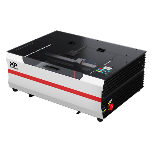
· For teams comparing a UV laser for medical devices, a Monport 6 W or 10 W UV galvo system can be placed on the sample-test shortlist because those power options are currently offered. That is a product-fit hypothesis, not a compliance claim. Confirm the current enclosure, lens, cooling, software, automation, and service coverage before issuing a purchase order.

Common Mistakes Make Good Equipment Look Inconsistent
· Testing a generic silicone sheet: it does not represent the final grade, pigment, cure, surface, or geometry.
· Optimizing only for darkness: the darkest mark may also have unacceptable roughness or chemical change.
· Using one parameter recipe for every color: optical response can vary substantially.
· Ignoring focus on curved parts: part-height variation can change line width and contrast across one logo.
· Calling a mark permanent after a finger-rub test: real lifecycle exposures must be reproduced.
· Treating color fill as part of laser qualification: the added material and its adhesion need their own controls.
· Assuming a machine is “FDA approved” for the application: the manufacturer validates the device and manufacturing process under the applicable quality system and regulatory framework.
Frequently Asked Questions
What is the best laser engraver for silicone?
A 355 nm UV laser is usually the first system to test for fine marks on heat-sensitive silicone. However, the best choice depends on the exact formulation, color, surface, geometry, desired contrast, and lifecycle exposure. A final molded-part trial is more reliable than choosing by wavelength or wattage alone.
Can laser engraving silicone produce a permanent mark?
It can, but permanence must be defined against the intended lifecycle. Test abrasion, cleaning agents, stretching or flexing, sterilization where applicable, aging, and machine readability before calling the mark permanent.
Can a UV laser mark every type of medical silicone?
No. UV is a strong first candidate, but contrast and surface quality depend on formulation, pigment, additives, cure, texture, and geometry. Test the released material grade and every controlled color family.
Does UV marking create no heat?
No. “Cold marking” means the interaction can limit bulk thermal damage compared with more heat-intensive processes. Excess energy, tight hatching, poor focus, or repeated passes can still discolor or roughen silicone.
Can a fiber laser mark silicone?
Sometimes, particularly when the formulation contains compatible pigments or laser-sensitive additives. Untreated silicone may provide weak or inconsistent absorption at 1064 nm, so sample testing is essential.
Is CO2 engraving suitable for silicone medical parts?
CO2 energy can strongly heat and ablate silicone. It may be useful in selected applications, but melting, charring, debris, and tactile surface change can make it unsuitable for delicate functional parts. Evaluate the intended use and marked location.
Will the mark survive cleaning or sterilization?
It may, but only lifecycle testing can support that conclusion. Use the actual cleaning agents, exposure conditions, cycle counts, and acceptance criteria associated with the device.
Do we need an enclosed system?
The installation must meet applicable laser-safety requirements and the organization's risk assessment. An engineered enclosure with interlocks is generally easier to control in a shared production or laboratory environment than an open beam path.
What should we send for a supplier sample test?
Send final molded parts from more than one production-representative lot, all required colors, the hardest geometry, artwork files, mark-position limits, lifecycle exposures, and written acceptance criteria.
Choose the Test Before Choosing the Machine
For laser engraving silicone tubes, masks, seals, earplugs, connectors, and other heat-sensitive medical components, UV is often the most credible starting process. Its advantage is controlled, fine marking with less unwanted thermal impact—not immunity from material variation or validation work.
The next step is to build a small qualification matrix using final parts, then ask suppliers to return both the samples and the complete process record. Compare readability, surface condition, function, lifecycle durability, cycle time, safety controls, software, and support. The machine that produces the darkest logo in a showroom is not necessarily the machine that produces the most defensible production process.
This article is informational and does not constitute regulatory advice. For FDA/ISO compliance decisions, consult a regulatory affairs professional.